

How PCB Depanelization Can Damage Tact Switches
A tact switch can pass incoming inspection, survive reflow soldering and respond normally during a panel-level electrical test, then become intermittent after the boards are separated. The resulting fault often looks like a weak switch: a button needs extra pressure, loses its click or occasionally fails to register.
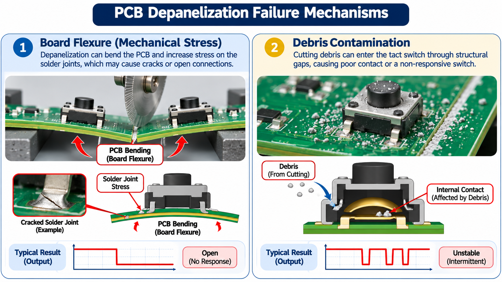
Before changing the switch model, an OEM or electronics manufacturing services (EMS) team should examine what happened between panel test and final assembly. PCB depanelization creates two distinct risks for mounted switches. Board deformation can load solder joints and nearby circuitry, while cutting debris can reach the small openings around a switch actuator. Both risks depend on the board design and the actual separation process.
The best time to control these risks is before the first production panel is built.
Two Failure Paths After Depanelization
Mechanical stress follows the board. When an operator bends a V-scored panel or breaks a routed tab, the PCB deflects. That movement creates strain in copper features, solder joints and components near the separation path. The risk is especially important where an SMT switch sits near the edge, the board is thin or poorly supported, or the separation tool loads the board unevenly. The actuator may still feel normal even when a fractured solder joint, lifted pad or damaged trace interrupts the electrical signal.
Contamination follows the cutting process. Routing, sawing, tab removal and edge finishing can produce particles. Openings around the actuator and housing of a non-sealed tact switch can provide a path into its mechanism. Alps Alpine specifically identifies board debris generated when separating assemblies with mounted tact switches as a contamination concern. Omron also warns that particles from PCB separation can attach to switches and interfere with electrical contact.
The distinction matters during failure analysis. Debris control cannot repair a fractured connection, and reducing board flexure alone cannot prevent particles from entering an unprotected switch.
Choose the Separation Method With the Switch in Mind
The panel drawing and the depanelization method should be reviewed together. A panel layout that improves throughput still needs to protect the components on each finished board.
V-scoring keeps straight-sided boards connected along a scored line. Controlled blade separation can be fast for volume production, but forcing boards apart by hand can introduce variable bending. Before approving V-scoring, check component height and tool clearance, distance from the score to nearby switches, panel support and the amount of deflection during separation.
Routed tabs with perforations support irregular outlines. Tab position matters: a tab close to a switch can concentrate local bending when it is snapped or cut. The remaining tab material can also affect how the board fits into its enclosure. Discuss tab number, location, breakout direction and any required edge finishing with the assembler.
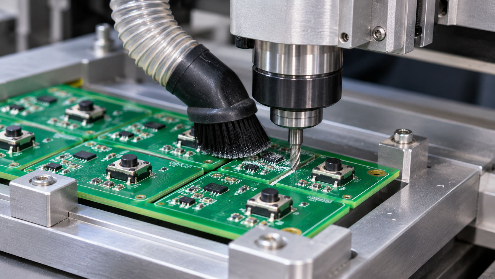
Fixture-supported routing uses a programmed tool path and dedicated board support. It can avoid the intentional bending associated with manual breakaway, but its results still depend on fixture design, tool condition, feed settings and extraction. Routing generates debris, so control both the mechanical load and the path taken by particles.
No method is automatically safe for every assembly. The correct choice depends on board thickness and outline, component placement, manufacturing volume, permissible mechanical strain and the capabilities of the production line.
Place Switches Outside the Highest-Risk Areas
A panel layout review should identify every tact switch near a V-score, breakout tab, board corner or narrow section of laminate. These areas can experience concentrated deformation as the final connections to the panel are released.
For each at-risk switch, review four features:
-
Distance from the separation feature. Confirm there is room for the cutting tool and enough separation between the switch solder joints and the region that bends. Published PCB manufacturing guides offer starting clearances, but those figures are not universal qualification limits for all switches and boards.
-
Board support. Evaluate whether the PCB is supported beneath and around the switch during the complete cut, including the moment when the last tab releases.
-
Mechanical load path. Avoid arrangements in which an operator must twist the populated PCB or press on the switch body to free the board.
-
Post-separation handling. Plan where the finished PCB will be placed. Unsupported stacking, gripping the board near the switch or pressing its actuator during handling can introduce damage after the cut is finished.
If the switch must sit close to the edge because of the enclosure design, treat its location as an explicit process-validation item. One prototype that survives hand separation does not establish a repeatable production process.
Control Dust Before It Reaches the Actuator
Manufacturers distinguish between switches designed to resist contamination and models with openings that can admit particles. Even a switch that looks enclosed from above may not be intended for a debris-heavy production process.
A practical contamination-control plan should address the whole work area:
-
Capture routing or cutting debris at the source using suitable extraction equipment.
-
Keep switches out of the direct path of chips and dust produced by the cutting tool.
-
Clean fixtures, trays and work surfaces so particles do not transfer from one board to the next.
-
Use approved, compatible protective coverings or process barriers when the switch manufacturer permits them. Confirm they do not foul the actuator or leave adhesive residue.
-
Inspect the actual switch opening and surrounding board after separation, rather than checking only the edge finish.
Do not assume that blowing compressed air across a switch is a safe cleaning method. It can redistribute particles and may drive debris deeper into openings. Likewise, do not wash a mounted switch unless the exact model and process have been qualified for washing.
A dust-resistant or sealed switch may be worth evaluating when exposure cannot be eliminated. However, the exact model and manufacturing process still require validation; a published environmental rating does not qualify a switch for every cutting or cleaning operation.
Test at Three Points, Not Just at the End
A final functional test can identify defective boards, but it may be too late to determine when damage occurred. For a new product introduction, establish comparison data at three points:
Before depanelization. On representative assembled panels, document the switch model and lot, panel position, electrical operation and tactile response. Use the same test conditions at each subsequent stage to create a meaningful baseline.
Immediately after depanelization. Repeat electrical and tactile checks before enclosure assembly. Look for changes associated with panel position, tool settings, separation method or production shift. Investigate newly intermittent signals before any rework changes the evidence.
After enclosure assembly. Retest with the keycap and housing fitted. A fault that appears only at this stage points the investigation toward actuator alignment, preload, mechanical interference or subsequent handling.
Use test conditions that represent the actual switch input circuit. A continuity buzzer may miss brief interruptions. Where needed, monitor the input waveform both at rest and during repeatable actuation, and compare any abnormal transitions with the physical condition of the assembly. Inspect switch terminals, solder joints, nearby pads and accessible openings under magnification. If the symptom is a change in tactile feel, compare operating force or travel using an appropriate test fixture.
When a problem appears only after separation, preserve unmodified failed boards for analysis. Reflowing a suspected joint or replacing the switch immediately may remove the evidence needed to distinguish mechanical damage from contamination.
Measure Board Strain When the Risk Justifies It
For high-volume or high-consequence assemblies, board-strain measurements can help compare depanelization fixtures and processes. IPC/JEDEC-9704A provides a strain-gauge measurement methodology for printed circuit assemblies and identifies depanelization as a process that can be evaluated. Its primary scope is board flexure and risks to mounted interconnects; it is not a tact-switch-specific qualification standard.
The guideline does not establish a universal pass/fail strain limit for tact switches. Set project acceptance criteria using board construction, component requirements and validation evidence. Instrument locations likely to see high strain, evaluate representative separation conditions and correlate the readings with electrical testing and physical inspection.
A reduction in measured strain helps demonstrate that a process change is effective against flexure. It does not establish that the switch is free of debris or protected from later handling loads.
What to Ask the EMS Provider and Switch Supplier
When post-depanelization failures appear, ask the EMS provider for evidence from the process before requesting a substitute switch. Review:
-
The controlled panel drawing, V-score or tab geometry and the intended separation method.
-
Switch location relative to the separation line and documented tool clearance.
-
How the board is supported throughout cutting and final release.
-
Dust-extraction, cleaning and inspection controls.
-
Test results before separation, immediately afterward and after enclosure assembly.
-
The switch manufacturer's guidance on debris exposure, cleaning, actuation loads and mounting.
-
The exact switch part number, revision and any approved process-protection or sealed variant.
If a switch change is justified, compare the PCB footprint, actuator geometry, soldering limits, operating force, electrical rating and contamination protection of each candidate. Similar body dimensions do not guarantee interchangeability. OEM teams reviewing tact switches for PCB assemblies should qualify samples through the actual assembly, depanelization and enclosure processes before approval.
Release the Process and the Component Together
Depanelization belongs in the switch qualification plan whenever tact switches are installed before the boards are separated. The component can be correct and still fail because of contamination, board bending or uncontrolled handling.
Before production release, document the approved panel design, separation method, fixture and extraction settings, inspection criteria and switch specification. Stage-by-stage testing then makes it easier to locate the point of failure, verify corrective action and avoid replacing a suitable component for a manufacturing-process problem.